- English
- Español
- Português
- русский
- Français
- 日本語
- Deutsch
- tiếng Việt
- Italiano
- Nederlands
- ภาษาไทย
- Polski
- 한국어
- Svenska
- magyar
- Malay
- বাংলা ভাষার
- Dansk
- Suomi
- हिन्दी
- Pilipino
- Türkçe
- Gaeilge
- العربية
- Indonesia
- Norsk
- تمل
- český
- ελληνικά
- український
- Javanese
- فارسی
- தமிழ்
- తెలుగు
- नेपाली
- Burmese
- български
- ລາວ
- Latine
- Қазақша
- Euskal
- Azərbaycan
- Slovenský jazyk
- Македонски
- Lietuvos
- Eesti Keel
- Română
- Slovenski
- मराठी
- Srpski језик

Hydraulic Flow Control Basics: What Engineers Need to Know
In any hydraulic system, flow rate—not pressure—determines actuator speed. Pressure provides force; flow controls how fast a cylinder extends or a motor turns. Understanding this distinction is the foundation of every well-designed hydraulic circuit, and it begins with effective flow control.
The Main Types of Flow Control Valves
The simplest devices, needle and throttle valves, may suggest that fixed restriction could provide adequate flow control. However, the significant evidence indicates that flow varies with load, given that flow through an orifice changes with pressure drop. In light of these findings, engineers could demonstrate that pressure-compensated valves appear to maintain a constant pressure drop across the orifice. Moreover, the key results may suggest that actuator speed remains steady even as load conditions change. Proportional valves go further using electrical signal for precise programmable control.
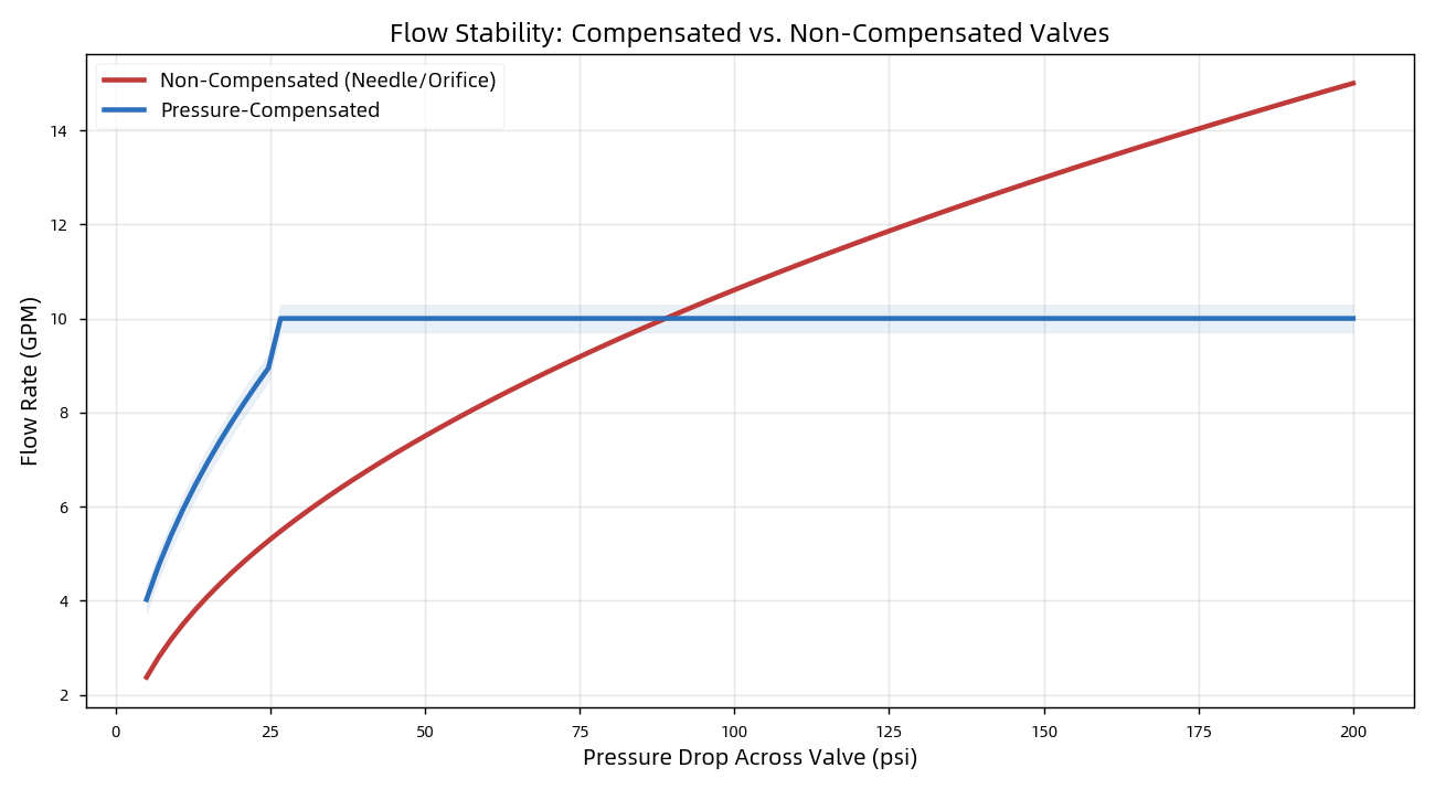
Compensated vs. non-compensated flow
Three Basic Speed-Control Circuits
Where the valve sits in the circuit matters:
● Meter-In – placed before the actuator; ideal for opposing loads, but cannot control runaway loads.
● Meter-Out – placed on the return line; creates back-pressure to safely control overrunning loads. The rule of thumb: "if in doubt, meter out."
● Bleed-Off – diverts surplus flow to tank; the most energy-efficient option, but less precise.
|
Circuit |
Best For |
Overrunning Loads |
Efficiency |
|
Meter-In |
Opposing loads |
No |
Low |
|
Meter-Out |
Vertical/overrunning loads |
Yes |
Low |
|
Bleed-Off |
Constant-pressure tasks |
No |
High |
Why Machining Precision Matters
Flow control performance may suggest that part quality could indicate the key determinant of overall system reliability. However, the significant findings demonstrate that a valve spool must slide freely yet seal tightly within its bore—often requiring tolerances as tight as ±0.001 mm and surface finishes of Ra 0.2–0.8 µm. Furthermore, the evidence could suggest that loose clearances appear to cause internal leakage, wasted energy, and heat accumulation. In light of these results, rough surfaces might indicate that seal wear and leakage could demonstrate critical failure pathways. Loose clearances waste energy; rough surfaces leak.
Your OEM Partner: Difon Machining
At Difon Machining, we manufacture precision hydraulic components—manifolds, valve bodies, spools, and fittings—to the exact tolerances flow control demands. With ISO 9001 and IATF 16949 certification, multi-process CNC machining, and an experienced engineering team, we support OEM customers from prototype to volume production.