- English
- Español
- Português
- русский
- Français
- 日本語
- Deutsch
- tiếng Việt
- Italiano
- Nederlands
- ภาษาไทย
- Polski
- 한국어
- Svenska
- magyar
- Malay
- বাংলা ভাষার
- Dansk
- Suomi
- हिन्दी
- Pilipino
- Türkçe
- Gaeilge
- العربية
- Indonesia
- Norsk
- تمل
- český
- ελληνικά
- український
- Javanese
- فارسی
- தமிழ்
- తెలుగు
- नेपाली
- Burmese
- български
- ລາວ
- Latine
- Қазақша
- Euskal
- Azərbaycan
- Slovenský jazyk
- Македонски
- Lietuvos
- Eesti Keel
- Română
- Slovenski
- मराठी
- Srpski језик

Why Are Hydraulic Components Essential for Industrial and Mobile Equipment?
Hydraulic Components are essential to industrial and mobile equipment because they control how pressurized fluid is generated, distributed, regulated, and converted into mechanical movement. From construction machinery and agricultural equipment to factory automation and material handling systems, hydraulic technology provides the force and controllability required for lifting, clamping, steering, braking, and other demanding operations. Components such as hydraulic valve blocks, manifold bodies, accumulator charging valves, and brake proportioning valves determine whether fluid reaches the correct actuator at the required pressure and flow rate.
Equipment performance depends on more than the hydraulic pump or cylinder. Internal passages, valve interfaces, sealing surfaces, threaded ports, and precision-machined bores all influence system response, leakage control, and operating reliability. Qingdao Difon Machinery Co., Ltd. manufactures custom hydraulic parts through precision machining and related production processes. Understanding the role of these components helps equipment manufacturers select suitable materials, define machining requirements, and build hydraulic systems that perform consistently under real operating conditions.
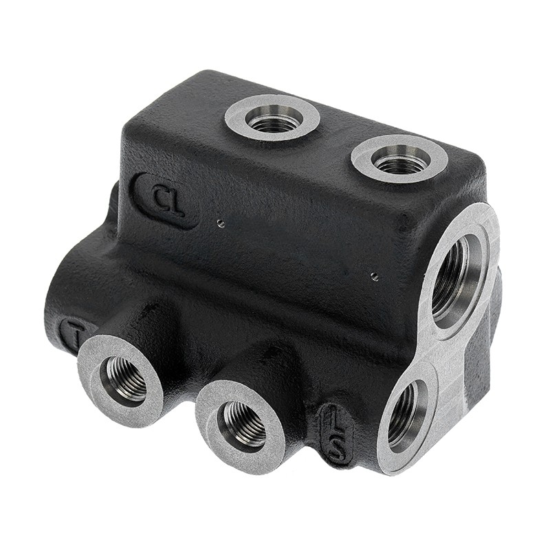
Table of Contents
1. Why Do Hydraulic Systems Depend on Precisely Designed Components?
2. How Do Key Hydraulic Parts Improve Industrial and Mobile Equipment Performance?
3. What Manufacturing and Quality Requirements Determine Component Reliability?
Why Do Hydraulic Systems Depend on Precisely Designed Components?
A hydraulic system transmits power through pressurized fluid. The pump supplies flow, control valves direct and regulate that flow, and actuators convert hydraulic energy into linear or rotary movement. Each part must perform its assigned function while working with the other elements in the circuit. A poorly designed passage, incorrectly positioned port, or unsuitable sealing surface can affect the performance of the entire system, even when the pump and actuator are correctly selected.
How Does Fluid Control Translate Into Equipment Movement?
Hydraulic systems are valued for their ability to deliver substantial force within relatively compact equipment layouts. When pressurized oil enters a cylinder, it acts on the piston area to produce linear force. When fluid drives a hydraulic motor, pressure and flow contribute to rotational torque and speed. The control circuit determines how much fluid reaches the actuator, in which direction it travels, and under what pressure conditions the equipment operates.
Different components perform specific functions within this circuit:
- Directional control valves determine the route taken by hydraulic fluid and control actuator movement.
- Pressure relief valves protect the circuit against pressure exceeding the defined setting.
- Flow control valves regulate actuator speed by controlling the amount of fluid passing through a circuit.
- Check valves allow flow in a designated direction while restricting reverse flow.
- Hydraulic manifolds connect multiple valves and internal passages in a compact arrangement.
- Accumulator charging valves support the charging and control functions associated with hydraulic accumulators.
- Brake proportioning valves help manage hydraulic pressure distribution in braking circuits designed for specific equipment.
The interaction between these components determines whether a machine starts smoothly, maintains a stable operating speed, responds accurately to control inputs, and handles changing loads. For example, a mobile excavator may need controlled boom movement while the operator simultaneously adjusts the arm and bucket. An industrial press may require repeatable pressure and movement during each production cycle. Both applications depend on a hydraulic circuit in which fluid paths and control elements are designed for the required operating sequence.
Why Are Manifolds and Valve Blocks Important to Hydraulic Circuit Design?
A hydraulic manifold provides a compact way to connect valves, ports, and internal fluid passages. Instead of relying entirely on separate pipes and fittings, a manifold can integrate several connections into one machined body. This arrangement can reduce external plumbing, simplify installation, and make the overall circuit more organized. It is especially useful when multiple hydraulic functions need to be controlled within a limited equipment space.
A valve block provides mounting locations and fluid connections for hydraulic control elements. Depending on the design, it may contain intersecting drilled passages, threaded ports, valve cavities, mounting faces, and sealing interfaces. These features must be positioned accurately so that the installed valves align correctly and the internal flow paths connect as intended.
Precision is important because an internal passage is not simply a hole through a metal block. Its diameter, position, straightness, surface condition, and relationship with intersecting passages can influence flow behaviour and component assembly. Incorrect drilling or machining may leave burrs, create restricted flow areas, or cause difficulties when valves and plugs are installed. Cross-port intersections also need suitable deburring and cleaning to prevent machining residues from entering the hydraulic circuit.
Difon identifies hydraulic manifold valve bodies and hydraulic valve blocks among its precision-machined product categories. Its published manufacturing information includes deep-hole drilling for passages with a length greater than 20 times the bore diameter, as well as multi-axis machining for complex port and mounting geometries. These capabilities are relevant to manifold designs that require accurate internal connections and carefully positioned interfaces.
What Happens When Hydraulic Components Are Not Matched to the System?
A component can be dimensionally acceptable in isolation but unsuitable for a particular hydraulic circuit. Port connections may not match the specified fittings, a valve cavity may not accommodate the selected cartridge, or a sealing face may not provide the required contact condition. These problems can lead to assembly delays, leakage, pressure loss, or unstable operation.
Common design and selection issues include:
- Incorrect port thread specifications, such as using an incompatible SAE, JIC, NPT, or BSPP connection.
- Insufficient passage dimensions that restrict the required flow rate.
- Inaccurate valve mounting locations that affect alignment and assembly.
- Unsuitable material selection for the operating pressure, temperature, fluid, or surrounding environment.
- Inadequate sealing surface quality that increases the risk of external or internal leakage.
- Insufficient cleaning that allows chips or abrasive particles to enter sensitive valve and actuator areas.
These issues explain why component specifications should be developed alongside the hydraulic circuit design. Engineers need to define the working pressure, flow rate, fluid type, temperature range, connection standard, installation space, and expected duty cycle before finalizing a component drawing. A clear specification gives the manufacturer a reliable basis for material selection and process planning.
Our machining approach begins with understanding the component's role in the circuit, rather than treating the part as an isolated metal shape. For OEM projects, the drawing, sample, port layout, and required interfaces provide the starting point for reviewing manufacturing feasibility. This helps connect the component's physical features with the operating requirements of the finished machine.
How Do Key Hydraulic Parts Improve Industrial and Mobile Equipment Performance?
Different hydraulic parts influence equipment performance in different ways. A manifold organizes fluid distribution, a valve body provides the interfaces needed for flow control, and an accumulator charging valve supports pressure management in an accumulator circuit. A brake proportioning valve serves a different purpose by managing pressure distribution in a braking system. Understanding these distinctions helps buyers specify the right part for the application instead of relying on a broad component name.
Where Are Hydraulic Valve Blocks and Manifolds Used?
Hydraulic valve blocks and manifolds are used in systems where multiple hydraulic functions must be controlled through a compact arrangement. Industrial machinery may use them to coordinate clamping, lifting, positioning, and pressing operations. Mobile equipment may use manifold assemblies to distribute oil to steering, boom, arm, travel, or auxiliary functions.
Consider several typical applications:
- Construction machinery: Excavators, loaders, and lifting equipment use hydraulic circuits to control movement under changing loads. Valve blocks organize connections between pumps, control valves, and actuators.
- Agricultural machinery: Tractors, harvesters, and planting equipment use hydraulic power for lifting implements, adjusting working positions, and operating auxiliary mechanisms.
- Industrial automation: Production lines, presses, and material handling systems rely on controlled hydraulic movement for clamping, positioning, and repetitive operations.
- Mining equipment: Hydraulic circuits operate heavy-duty mechanisms where vibration, dust, load variation, and limited installation space place additional demands on component design.
- Special-purpose machinery: Custom equipment may require a manifold layout that combines several control functions within a specific installation envelope.
A manifold can reduce the number of external connections when compared with a circuit assembled entirely from separate pipes and fittings. Fewer external joints may simplify installation and reduce potential leakage points, although the actual result depends on the circuit layout, sealing design, assembly quality, and maintenance practices. Internal passages must still be designed to avoid unnecessary restrictions, sharp transitions, and unsuitable flow paths.
For an OEM manufacturer, the manifold is also an important interface between hydraulic engineering and equipment packaging. Its mounting holes, port orientation, overall dimensions, and valve positions need to fit the surrounding structure. If the block is too large, it may interfere with other components. If the ports are positioned incorrectly, hose routing and service access may become difficult. These are practical design considerations that should be resolved before production.
How Do Accumulator Charging Valves Support Hydraulic Systems?
Hydraulic accumulators store energy by holding pressurized fluid against a compressible gas or another energy-storage mechanism, depending on the accumulator design. They can help absorb pressure fluctuations, provide supplementary flow during peak demand, compensate for leakage, and maintain pressure in selected circuits. An accumulator charging valve is used in systems that require controlled charging and management of accumulator pressure.
In construction machinery and industrial equipment, accumulator-related circuits may support functions such as emergency energy supply, pressure stabilization, or temporary peak-flow assistance. The exact role depends on the circuit design. The charging valve must be compatible with the accumulator arrangement, pressure requirements, port connections, and fluid specifications. A mismatch can affect charging behaviour or create an unsafe operating condition.
Important engineering details include:
- Rated working pressure and the maximum pressure permitted by the system design.
- Connection dimensions and thread standards for the accumulator and hydraulic circuit.
- Internal bore dimensions and sealing geometry.
- Material compatibility with the hydraulic fluid and operating environment.
- Required response and control behaviour as defined by the equipment circuit.
- Inspection and testing requirements for the finished valve body or assembly.
Difon publishes a custom accumulator charging valve offering and describes production from raw casting through precision machining. Its product information also states that selected machining operations can achieve dimensional tolerances down to 0.005 mm and internal bore tolerances down to 0.002 mm. These figures are product-page claims for the specified machining context, not universal tolerances for every valve or every feature. The drawing and inspection plan should identify which dimensions require these levels of control.
Why Does a Brake Proportioning Valve Matter in Mobile Equipment?
Braking performance is a safety-critical function in mobile machinery and vehicles. A brake proportioning valve is designed to manage hydraulic pressure distribution within a braking circuit. Depending on the system architecture, pressure distribution may need to be controlled to help balance braking forces under different load conditions. The exact function and calibration depend on the vehicle or machine design and must follow the applicable engineering requirements.
For a manufacturer, the valve body must provide accurate internal passages, reliable sealing interfaces, and correctly machined connection features. The body material and manufacturing method must be appropriate for the specified pressure and environmental conditions. If a bore is out of tolerance or a sealing surface is damaged, the valve may not operate as intended. Machining quality is therefore one part of the complete brake system safety process, alongside valve design, calibration, testing, and vehicle-level validation.
Difon lists brake proportioning valves among its hydraulic product categories and describes the use of casting and precision CNC machining for hydraulic valve body manufacturing. This type of production route is relevant where a component combines a cast or formed blank with machined passages, ports, and functional surfaces. The selected material, casting quality, machining allowance, and inspection method should all be defined for the particular design.
How Should Buyers Compare Different Hydraulic Part Types?
The following table summarizes the role of several component categories and the main technical details that buyers should confirm. It is intended as a selection guide, not a substitute for the equipment manufacturer's hydraulic circuit specification.
| Component category | Main function | Typical equipment applications | Important specification checks |
| Hydraulic valve block | Provides valve mounting interfaces and internal fluid passages | Construction machinery, agricultural machinery, industrial systems | Port layout, bore dimensions, mounting features, pressure rating, sealing surfaces |
| Hydraulic manifold | Connects multiple hydraulic functions through an integrated passage network | Automation equipment, mobile machinery, heavy-duty hydraulic systems | Flow path design, port standards, passage intersections, pressure drop, cleanliness |
| Accumulator charging valve | Supports controlled charging and pressure management in accumulator circuits | Construction equipment, industrial automation, heavy machinery | Pressure requirements, bore tolerances, connection details, sealing geometry |
| Brake proportioning valve | Manages hydraulic pressure distribution within a specified braking circuit | Mobile equipment and vehicle braking systems | Valve body accuracy, pressure requirements, sealing, calibration and system validation |
| Hydraulic motor components | Support the conversion of hydraulic energy into rotary mechanical output | Industrial drives, agricultural machinery, mobile equipment | Material, machining interfaces, shaft geometry, bearing and sealing requirements |
The right part is the one that matches the actual circuit, not necessarily the one with the most elaborate description or the smallest quoted tolerance. A hydraulic block for a low-flow auxiliary function may have different design priorities from a high-flow manifold serving several actuators. Similarly, a brake-related valve requires safety and validation considerations that should not be replaced by ordinary dimensional inspection alone.
Our engineering review considers the intended function, port arrangement, material requirements, and critical dimensions before a manufacturing route is confirmed. For custom orders, drawings and samples help establish the relationship between the machined component and the equipment assembly. This is particularly useful when a part must replace an existing component or fit within a restricted installation space.
What Manufacturing and Quality Requirements Determine Hydraulic Component Reliability?
Hydraulic component reliability is built through a series of manufacturing decisions. Material selection establishes the starting properties of the part, machining creates its functional geometry, surface treatment protects or modifies the surface, and inspection checks whether the finished component meets the drawing. For parts containing internal fluid passages, cleanliness is equally important because even small machining residues can affect sensitive hydraulic elements.
Which Materials Are Used for Different Hydraulic Applications?
Material selection should reflect pressure requirements, mechanical loading, corrosion exposure, weight targets, machinability, and compatibility with the hydraulic fluid. There is no single material that is best for every valve body or manifold. The chosen grade must also be suitable for the manufacturing process, including casting, drilling, milling, turning, heat treatment, and surface finishing.
Common material groups include:
- Carbon steel: Often selected for general hydraulic parts where strength, machinability, and cost need to be balanced. The specific grade should be matched to the required mechanical properties and service conditions.
- Alloy steel: Used where higher strength, wear resistance, or specific heat-treatment properties are required. Material grade and heat-treatment condition should be confirmed against the design.
- Cast iron: Used for certain valve bodies and hydraulic blocks because casting can create a practical near-net shape before machining. Casting quality and internal soundness are important for pressure-containing applications.
- Stainless steel: Considered where corrosion resistance is a priority, although the grade must be selected according to the fluid and surrounding environment.
- Aluminum alloys: Useful where reducing component weight is important, including selected mobile equipment applications. Strength, thread design, wear surfaces, and pressure requirements must be checked carefully.
- Titanium alloys: May be considered for specialized applications requiring a particular strength-to-weight or corrosion-resistance profile, subject to cost and machining considerations.
The material list published for Difon's hydraulic machining services includes carbon steel, alloy steel, stainless steel, aluminum alloys, cast iron, and titanium alloy options across its product information. Availability and suitability depend on the specific component, drawing, and order requirements. A material should not be selected simply because it appears in a general capability list; the exact grade, heat-treatment condition, and required certification should be confirmed for the project.
How Do CNC Machining and Deep-Hole Drilling Affect Fluid Performance?
Hydraulic valve bodies and manifolds often contain complex internal passages that connect ports located on different faces of the component. CNC milling and drilling create these features, while turning and other machining operations produce round interfaces, threads, bores, and sealing surfaces. Multi-axis machining can reduce repeated setups for complex geometries and help maintain the relationship between different features.
Deep-hole drilling is especially important when a design requires a long internal passage. The bore must follow the specified position and direction while maintaining the required diameter and surface condition. If the hole deviates too far from its intended path, it may approach another passage, reduce the wall thickness, or create an unexpected connection. Bore inspection and suitable cleaning procedures help confirm that the passage meets the drawing requirements.
Difon's published hydraulic machining specifications include the following process references:
| Manufacturing process | Published technical information | Relevant quality checks |
| Deep-hole drilling | Diameter range 3–50 mm; depth up to 1000 mm; stated straightness 0.1 mm per 100 mm | Bore inspection, surface roughness checks, passage verification |
| Multi-axis CNC machining | Published tolerance ±0.005 mm; positional accuracy ±0.005 mm; surface finish Ra 0.2–0.8 μm | CMM measurement, prototype inspection, process monitoring |
| Port and thread machining | SAE, JIC, NPT, and BSPP thread standards are listed | Thread gauges, dimensional checks, air or pressure testing where specified |
| Heat treatment and surface engineering | Nitriding, hard chrome plating, and phosphate coating are listed | Hardness checks and coating thickness verification where applicable |
These are published process specifications and should be applied only where they match the relevant part and manufacturing route. A general tolerance statement does not mean every dimension on every hydraulic product is machined to the same value. The drawing should identify critical features such as valve cavities, bore diameters, port positions, sealing faces, and mounting datums. Inspection methods can then be selected for those features.
Why Are Surface Finish and Cleanliness Critical to Sealing?
Hydraulic systems rely on sealing interfaces to contain pressurized fluid. Depending on the design, a valve body may use O-rings, metal-to-metal contact, cartridge interfaces, plugs, or other sealing arrangements. The surface condition around these features affects how the seal sits and how well it performs. Excessive roughness, scratches, burrs, or machining marks may create leakage paths or damage a seal during installation.
Surface finish requirements should therefore be specified for functional areas rather than applied as one universal value to the entire component. A non-sealing external face may not require the same finish as a precision bore or valve mounting surface. Grinding, honing, or other finishing methods may be used where the design calls for a controlled surface condition. The appropriate process depends on the material, geometry, seal type, and drawing requirements.
Cleanliness is just as important. Drilling and milling can leave chips, burrs, cutting fluid, and fine particles inside passages. If these contaminants remain in the finished part, they may travel into valves, pumps, cylinders, or other sensitive components. Cross-drilled holes are particularly important because burrs can remain where two passages intersect. Deburring, flushing, drying, and protected packaging should be included in the production plan where the application requires them.
Surface treatments such as nitriding, hard chrome plating, phosphate coating, black oxide, or other specified finishes may be used to meet particular requirements. They are not interchangeable. Some treatments improve surface hardness or wear behaviour, while others provide corrosion protection or alter friction characteristics. The selected process must be compatible with the base material, dimensional tolerances, sealing surfaces, and operating fluid. Any coating thickness that affects a fitted interface should be considered during machining allowance planning.
How Should Finished Parts Be Inspected Before Delivery?
Inspection should be linked to the component drawing and the risks associated with its function. A visual check alone is not enough for a precision hydraulic part containing internal passages and sealing interfaces. Dimensional inspection, thread verification, surface checks, cleanliness assessment, and pressure-related tests may all be required depending on the product specification.
A practical inspection plan may include the following checks:
- Material verification: Confirm the ordered material grade and any specified heat-treatment condition using the required supplier documentation.
- Dimensional inspection: Measure critical bores, port locations, mounting surfaces, thread features, and datum relationships.
- Geometric inspection: Check positional accuracy, perpendicularity, flatness, and other geometric tolerances where specified.
- Surface inspection: Examine sealing faces, bores, and external surfaces for scratches, burrs, corrosion, or machining defects.
- Thread inspection: Use suitable gauges to verify thread form and size against the specified connection standard.
- Cleanliness verification: Check that passages are free from chips, loose particles, and unacceptable processing residues.
- Functional or pressure testing: Conduct tests where required by the part drawing, customer specification, or applicable validation procedure.
Difon's published production information identifies equipment such as a coordinate measuring machine, profile projector, hardness tester, and surface roughness tester. Its hydraulic machining page also describes CMM verification, thread gauge inspection, air pressure testing, flow testing, and pressure testing as relevant quality assurance methods. The exact checks required for an order should be agreed in advance, including sampling frequency, acceptance criteria, and documentation.
Our factory treats critical dimensions and internal cleanliness as connected quality requirements. A bore may meet its diameter tolerance but still require further checks for surface condition, straightness, or cleanliness. Similarly, a threaded port may pass a thread gauge inspection while still needing confirmation of its sealing interface. The inspection plan should reflect how the part will function after installation.
What Information Should OEM Buyers Provide for a Custom Order?
Accurate input information reduces uncertainty during quotation and production. Buyers should provide a current 2D drawing, 3D model, physical sample, or a combination of these where available. The documents should identify the material, dimensions, tolerances, port standards, surface treatment, and any functional test requirements. If a component is intended to replace an existing part, the buyer should also clarify whether the design is an exact replacement or whether modifications are permitted.
Before confirming an order, it is useful to establish:
- Equipment type and the function performed by the component.
- Working pressure, maximum specified pressure, and expected flow conditions.
- Hydraulic fluid type and operating temperature range.
- Material grade and any heat-treatment requirement.
- Port thread standards, bore dimensions, and sealing arrangements.
- Critical dimensional and geometric tolerances.
- Surface treatment, coating thickness, and areas that must remain untreated.
- Required inspection reports, pressure tests, and traceability documents.
- Order quantity, prototype requirements, packaging, and delivery expectations.
For custom parts, the quotation should distinguish between standard machining capability and project-specific performance requirements. A quoted dimensional tolerance does not automatically establish a component's pressure rating, fatigue life, or suitability for a complete hydraulic system. Those characteristics depend on material properties, wall thickness, design calculations, manufacturing quality, and validation under the intended operating conditions.
Qingdao Difon Machinery Co., Ltd. provides OEM and ODM machining services and lists hydraulic valve blocks, accumulator charging valves, brake proportioning valves, and manifold-related products within its hydraulic product range. Its wider manufacturing resources include CNC machining and inspection equipment used for precision metal components. Buyers can use the drawing review stage to confirm which machining operations, materials, surface treatments, and inspection records are appropriate for the particular order.
Conclusion
Hydraulic Components are essential because they manage fluid distribution, pressure control, energy storage, and mechanical movement across industrial and mobile equipment. Valve blocks and manifolds organize complex hydraulic circuits, accumulator charging valves support pressure management, and brake proportioning valves perform important functions in designated braking systems. Their reliability depends on correct design, suitable materials, precision machining, effective sealing, clean internal passages, and inspection against the actual application requirements.
For OEM manufacturers and equipment engineers, selecting the right component begins with a clear understanding of the hydraulic circuit and the part's operating conditions. Qingdao Difon Machinery Co., Ltd. welcomes enquiries for custom hydraulic valve blocks, manifold bodies, accumulator charging valves, brake proportioning valves, and related precision-machined parts. Contact our team with your drawings, material requirements, and technical specifications to discuss a suitable manufacturing and inspection plan for your next industrial or mobile equipment project.
Frequently Asked Questions
1. What is the difference between a hydraulic valve block and a hydraulic manifold?
A hydraulic valve block generally provides the mounting interfaces and internal passages required to install and connect hydraulic valves, while a manifold is an integrated fluid-distribution body designed to connect multiple parts of a hydraulic circuit. The terms can overlap in industry usage, but the actual design, port arrangement, valve interfaces, and circuit function determine the component's role in a particular system.
2. How does machining accuracy affect hydraulic valve body performance?
Machining accuracy affects bore dimensions, valve alignment, port positioning, thread fit, and sealing interfaces. If a critical feature is outside its specified tolerance, the result may include assembly problems, restricted flow, internal leakage, or inconsistent valve operation. Accuracy must be evaluated against the drawing and functional requirements, with suitable measurement methods selected for each critical feature.
3. Which materials are commonly selected for hydraulic valve blocks and manifolds?
Common material options include carbon steel, alloy steel, cast iron, stainless steel, and aluminum alloys. Carbon and alloy steels are considered where strength and mechanical properties are important, cast iron is used for suitable cast valve bodies, stainless steel may be selected for corrosion-sensitive environments, and aluminum alloys can reduce weight in selected mobile applications. The exact grade must be confirmed against pressure, fluid compatibility, temperature, machining, and design requirements.
4. Why is internal cleanliness important after machining hydraulic parts?
Machining can leave metal chips, burrs, abrasive particles, and cutting-fluid residues inside drilled passages and threaded ports. If these contaminants enter a hydraulic circuit, they may interfere with valve operation, damage close-fitting surfaces, accelerate wear, or block small flow paths. Deburring, flushing, drying, inspection, and protected packaging help reduce contamination risks before installation.
5. What information should buyers provide when requesting a quotation for custom hydraulic parts?
Buyers should provide a current drawing or 3D model, material grade, dimensions, critical tolerances, port and thread standards, working pressure, hydraulic fluid, operating temperature, surface treatment, and required inspection or testing criteria. Equipment application, order quantity, prototype needs, and packaging requirements are also useful. Complete information allows the manufacturer to assess process feasibility, identify critical features, and prepare a quotation based on the actual component requirements.